A teach pendant is, in the words of ISO 10218-1, a hand-held unit linked to the control system with which a robot can be programmed or moved. It is also one of the most safety-critical human-machine interfaces in the factory: an operator carrying it steps inside the safeguarded space to jog, teach and verify points at close range, and the pendant's enabling and emergency-stop devices are the last line between a moving arm and a person. As pendants move from tethered cables to wireless and tablet-style mobile units, their battery stops being a convenience and becomes part of the functional-safety chain. This first paper on nickel-metal hydride power for wireless teach pendants explains the working principle and the resulting load profile. It works through the three-position enabling device that permits motion only in its middle position, the emergency stop that commands a controlled stop, the mode switch that selects reduced-speed teaching, and the wireless link whose loss must force a safe state. It then dissects the electrical load: a dominant touch-display backlight, a processor rendering 3-D robot models, a wireless radio with receive and transmit phases, and - above all - the safety circuitry that must remain powered and deterministic at every state of charge, because a pendant that simply switches off in a worker's hand inside the cell is itself a hazard. Real robot documentation anchors the safety behaviour, from the explicit three-position logic of collaborative-robot pendants to emergency stops that remove power from the actuators as a Stop Category 1 event.
Commissioning and teaching require a human to enter the robot's reach and move it through desired positions, define waypoints, tune speeds and verify paths step by step. ISO 10218-1 defines the pendant as the hand-held programming and jogging unit; ISO 10218-2 sets the requirements for the integrated robot system, including the safeguarded teaching workflow in which automatic operation is inhibited, a key-selected teach mode is selected and motion is permitted only while an enabling device is held.
The pendant therefore carries a distinctive set of controls: a large display with jog and programming interface, a mode selector, a prominent mushroom emergency stop, and one or more three-position enabling (dead-man) switches gripped while jogging. On a wireless pendant all of these, plus the radio that carries jog and safety signals, must run from an onboard battery while behaving with the determinism of a wired safety device.
The three-position enabling device, specified for switchgear in IEC 60947-5-8 and required by ISO 10218, has three stable mechanical states with deliberately non-intuitive logic: position 1, fully released, permits no motion; position 2, the middle position reached by light grip, enables motion at reduced teach speed; and position 3, fully squeezed in a panic reflex, again permits no motion. Releasing or over-gripping both stop the robot. Manufacturers are explicit that the enabling device is an operational control, not an emergency stop, and that freedrive or jog is active only in position 2.
This logic is implemented through dual-channel, fault-detecting contacts or safety inputs, and on a wireless pendant the state of those channels must be transmitted with the low latency and high integrity of a safety communication link. From a power standpoint the safety input chain draws a small but non-negotiable continuous current: it must be alive, debounced and transmitted correctly at any battery state, which is why a teach pendant cannot be designed like a consumer phone that simply dies at zero percent.
The pendant emergency stop follows ISO 13850 and, per IEC 60204-1, achieves a defined stop category; collaborative-robot documentation describes pressing the pendant E-stop as a Stop Category 1 in which the joints are commanded to stop and, once a monitored standstill is reached, power is removed from the actuators and tool outputs. In teach mode, speed is limited to a reduced value - ISO 10218 caps jogging at slow speed, widely implemented at no more than 250 mm/s - to keep a close-range operator safe.
These functions shape the battery requirement in a specific way: pressing E-stop or releasing the enable must always succeed, and the pendant must retain enough reserve to transmit the stop command, receive acknowledgement and indicate the resulting state. A battery architecture that reserves a guaranteed safety reserve below its 'operator discharged' level is therefore mandatory, not optional.
Going wireless removes the cable but adds a failure mode a wired pendant never has: loss of the radio link. Machine safety practice under IEC 60204-1 and robot safety standards require that interruption of a wireless control link results in a safe stop, with the robot halting if a valid, timely enabling or command message is not received within a watchdog window. The pendant and controller therefore exchange safety telegrams at a fixed rate, and either side declaring the link lost commands the safe state.
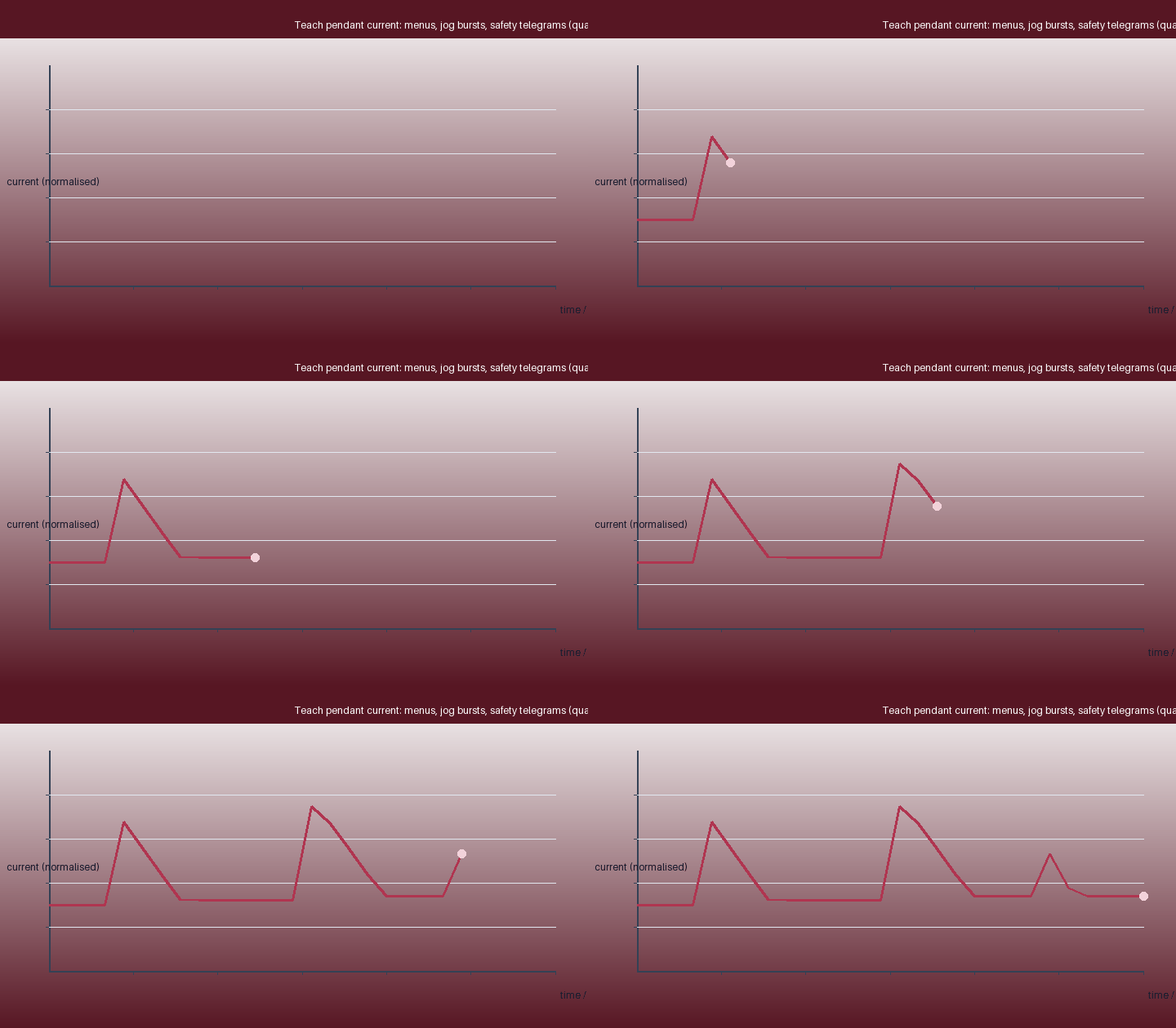
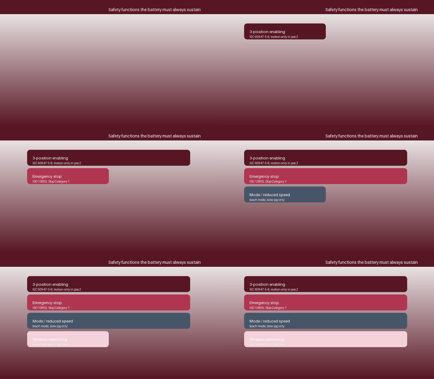
The radio contributes a characteristic load - a continuous receive phase with periodic transmit peaks carrying jog values and safety-channel states - and the battery must support those peaks without a brown-out that the controller would interpret as link loss. The first animated figure traces the pendant current through a teaching session, contrasting the display-and-render baseline, jog bursts and safety telegrams; the second layers the safety functions the battery must keep alive.
A modern pendant's energy is dominated by its large, bright touch display and the graphics processor rendering the robot and its workspace; backlight dimming and screen time-out are the main energy levers. Behind that sit the application processor, the wireless radio, backlit keys and the low-power but always-on safety input chain. Unlike a tablet, the pendant also drives audible and tactile feedback and must wake instantly when the enabling switch is gripped.
The load is bursty and interactive - long quiet periods of menu use punctuated by jogging sessions with high screen brightness and continuous radio traffic - but it is bounded by a hard floor: whatever the average current, the safety functions and the link watchdog must keep working down to a defined low-battery threshold, below which the pendant warns, requests a controlled end to teaching and finally inhibits motion rather than dying mid-jog.
The analysis yields a battery specification quite unlike a consumer device: enough energy for a realistic teaching or maintenance shift with the display at working brightness; low internal resistance for radio and processor peaks without rail disturbance; a guaranteed, separately budgeted safety reserve that keeps the enabling chain, E-stop and link telegrams alive long enough to stop the robot and hand control back cleanly; an accurate, deterministic state-of-charge indication; and industrial temperature and drop tolerance. The second paper turns this into a concrete pack design and compares nickel-metal hydride honestly with the lithium-ion cells used in consumer tablets; the third maps the ISO 10218, IEC 60204-1, functional-safety, radio and battery evidence a pendant must carry.
Designing the pendant battery as a safety-related subsystem - rather than a commodity power source - is the discipline that prevents the most dangerous failure a wireless teaching device can have: going dark in the hand of an operator standing inside the robot's reach.
Weijiang Power designs and manufactures sealed nickel-metal hydride cells and matched industrial packs for remote, off-grid and safety-related equipment, and supports OEM partners with IEC 61951-2 performance files, IEC 62133-2 safety evidence, pulse-load characterisation, wide-temperature testing and charger/pack co-validation. Tell us your duty cycle, peak current, temperature envelope, autonomy target and the standards your product must meet, and our engineers will specify a cell-and-pack combination that protects runtime, reliability and service life. Review the range on the products page.


